Today I will talking about my experience with my multi-copter i/o shield and where I'm going with it. Over a year ago I built my first MIOS (Link). This post is one of the most popular on my blog.
 |
| The original MIOS |
It worked great as an interface for the working with the data buses on the Arduino Due, but resistor based voltage divider for dealing with the RC input was really sub-optimal. It also only used 3.3v pulses to control the ESC/servos, which again is not the greatest.
Having used version 1 for over an year now, I have decided to make a second version. This version MIOSv2, brings a whole new level of flexibility and usefulness to the Due platform.
I have replaced the resistor voltage divider with "real" logic level voltage translator. This unit is the TI TSX0108E signal translator. I have used two of these units on the new board. This gives me 16 channels of 5v I/O (14x or on the right angle header and 2x are next to the lower translator ship). And since the chips are automatically bidirectional, this signal voltage translation is invisible. Yes, this means that if you decide to, you could attach 16 servos by only using the normal Arduino configuration and it will work without any additional consideration. If you want to alternate input and output every other pin, you can do that. If all you want are inputs, again, it's as easy as writing your program to use the associated pins as inputs.
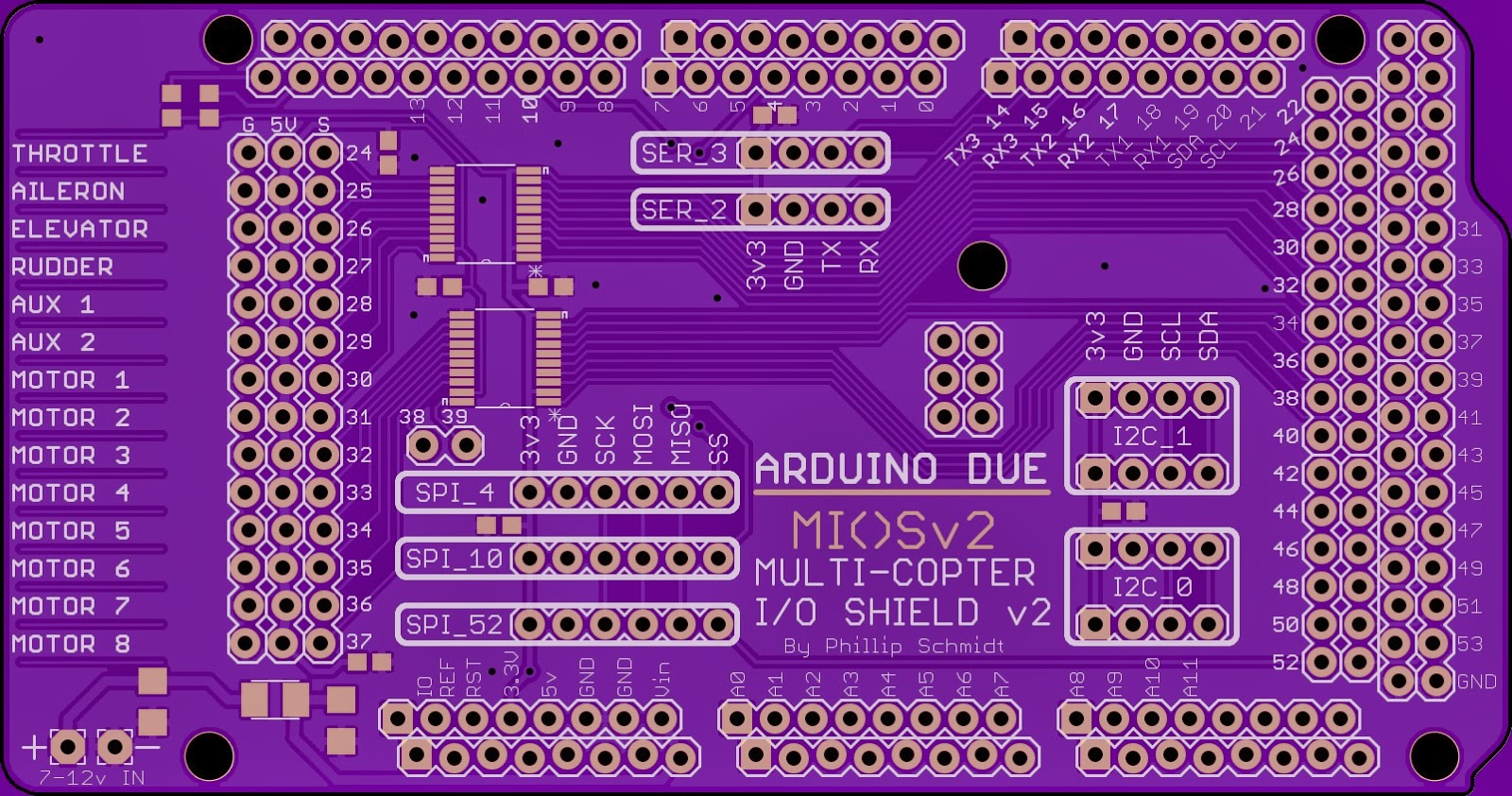
 |
| New MIOSv2 before adding the components. |
These 5v I/O are connected to Arduino pins 24 through 39. This mean that none of the special function pins are obstructed by this functionality. All of the PWM, DAC, ADC, CAN, I2C, SPI, and Serial pins are completely available to use even if you employ every single 5v I/O.
 |
| Complete MIOSv2 attached to an Arduino Due |
Like my previous version, I have grouped the major I/O buses with ground and 3.3v power. This gives you three SPI, 2x of each of the two I2C (aka TWI, or Wire), and both Serial 2 and Serial 3. I don't break out Serial 1 as it is used for communication to the Aduino software (but if I needed it it would be trivial to grab it from the perimeter and get the ground and 3.3v from any other group). All of the I/O pins around the perimeter are brought to the inside with an 0.1" spacing to make it easy to solder wires/headers to use them.
I have also added solder points for bringing power to the shield to power the Due independent of the power jack or USB port. This power input is run through a PI filter to reduce the electrical noise from adjacent motors, ESC, servos, radios etc...
I have made the decision to sell these as there has been an large degree interest in the original version. I did not want to sell that version as I didn't feel it was really as good as it should be. This new version fixes all of the reservations I had with the original and works perfectly. The initial batch is in manufacturing and testing. I have started to develop a store front for my long term sales, but in the short term I will probably sell the initial batch on eBay or directly to get these out in the field while my store is being developed. If you are interested please send an email to PhilsTechCorner@gmail.com. I will be selling this initial batch for $20 each (Future production runs will be $30 each). These are 100% guaranteed to function perfectly, the only difference in this initial batch is that all of the SMD components are hand soldered and some of the printing on the boards is a little lighter than I would have preferred. Orders are first-come-first serve and should ship out by last week of January. Arduino Due sold separately.
That is all for now. Let me know if you have any questions.
Thanks for reading and please sign up on the right if you want to be automatically notified when I post more updates.
~Phillip
<< Previous Quadrotor Post | Next Quadrotor Post >>
No comments:
Post a Comment